Old Electrical Equipment - Henley Metal Fusebox
Metal cased fusebox with cartridge fuses and a single MCB.
Exterior
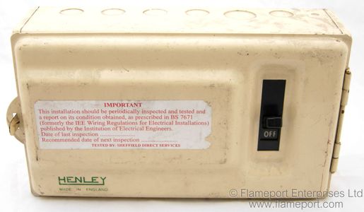 A metal cased fusebox finished in cream coloured paint.
The front has the 'Henley' logo on the lower left corner.
The main switch is accessible through the cover, which is held closed by a small spring tab on the left side.
Sides and Top
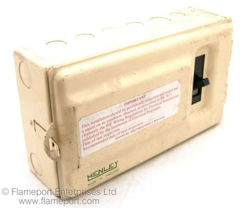
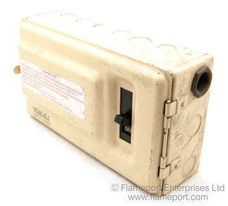 There are numerous knock-out holes for cable entries.
In this example, only one hole on the right was used, which was for the incoming supply wires.
Back
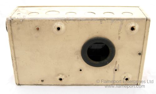 Four holes to secure the box to a wall or panel.
All of the circuit wiring entered through the large round hole, which is fitted with a rubber grommet.
Door Opened
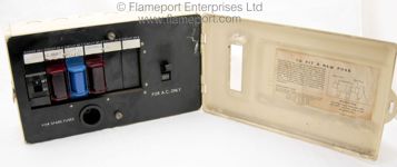 The hinged door opens to reveal the fuses inside.
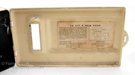
The lid has a paper label with fuse replacement instructions.
Front panel
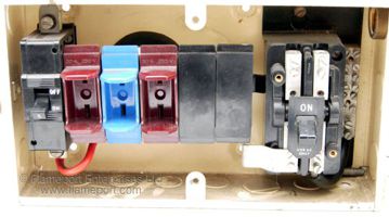
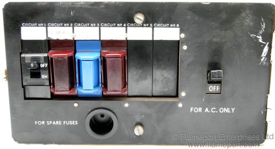 There are 6 ways for circuits, only four of which are used here.
Circuit 1 is a 5A MCB, the others are cartridge fuses rated 30A, 15A and 30A.
Circuits 5 and 6 are not used, and have blank plates fitted.
The round hole below the circuit devices is storage for spare fuses.
Devices
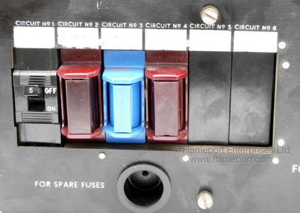
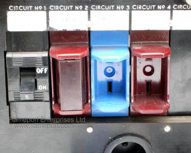 The first circuit is marked 'Lights' and is fitted with a 5A MCB.
2 is 'I Heat' with a 30A fuse, 3 is 'Ring Main' with a 15A fuse, and 4 is 'Cooker' with a 30A fuse.
It is likely 2 and 3 are transposed, since 15A is a common rating for an immersion heater, and ring circuits would have a 30A fuse.
Fuses
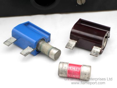 The fuses are BS1361 cartridge types, and fit into small plastic holders with flat blades.
These are similar in design to the larger Henley cutout fuse holders.
The 15A and 30A types are physically different sizes to prevent them being installed in the wrong position.
Main Switch
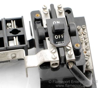
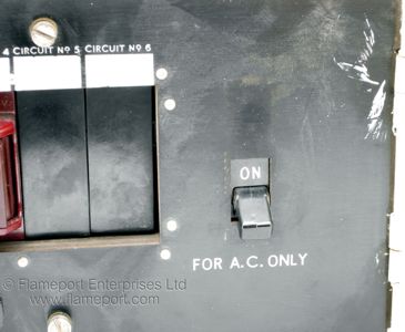 Unusually, there is no maximum rating marked on the switch. The only markings are the ON and OFF legend and 'For A.C. Only'
The neutral bar can be seen to the right of the switch.
Inside
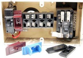 The fuses just pull out. The plastic shields are only held in place by the front panel.
Incoming connections
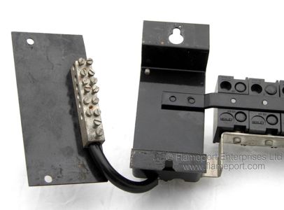
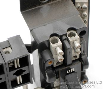 Incoming supply connects to the two terminals at the top of the main switch.
The neutral bar for outgoing circuits can be seen behind and to the right of the switch.
The second picture shows the neutral bar and support plate folded out, and the back of the switch mounting plate.
Chassis - Front and Back
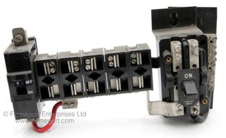
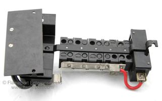 This appears to be a factory assembled unit including the 5A MCB.
The loose plate behind the main switch holds the neutral bar, and another insulated plate fixes behind this to prevent the neutral bar shorting onto the metal case.
Chassis - Top and bottom
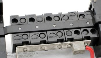
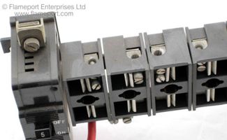 Outgoing circuits connect to the terminals on the top of each fuseway. Note the dual screws to secure circuit wires.
The MCB has a large fully exposed terminal on the top, and has a single screw with a wire clamp.
MCB connection
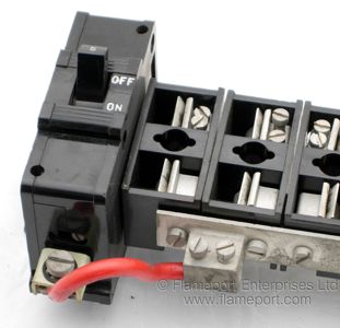 The MCB connects via a red insulated wire, the terminal for which is a part of the busbar.
This design prevents any additional MCBs being fitted, or changing the MCB for a fuse.
Box
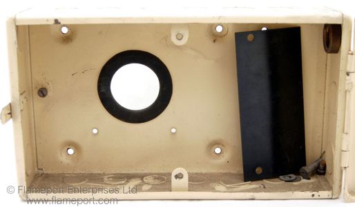 The metal box has the hinged lid permanantly attached. The black plate is an insulator which fits behind the main switch.
The single earth bolt was located in the lower right corner, where the loose screws are.
Front panel
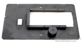
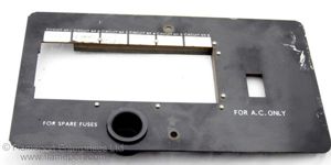 The front panel is a plastic sheet with wooden strips fixed around the opening for the fuses.
The round storage compartment for spare fuses is a separate plastic moulding.
The panel is secured with two screws.
Instruction Label
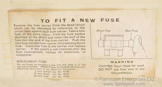 The lid contains a paper label which describes how to replace fuses.
Although the actual process of replacing the fuse is described in detail, it does not indicate how the fuse holder should be removed from the fusebox, and neither does it state to switch the power off first.
Instructions
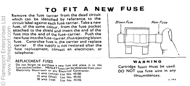 A reimaged version of the instruction label.
