Old earth-leakage circuit breakers (ELCB)
All of the items here are obsolete, and are displayed here as a reminder of how electrical installations used to be done.
In this section
Principle of operation
Significant flaws
Video
Obsolete Chilton earth leakage circuit breaker
Obsolete Ottermill Chilton earth leakage circuit breaker
Obsolete Crabtree earth leakage circuit breaker with red test button
Obsolete Crabtree earth leakage circuit breaker with yellow test button
Old GEC 'ELF' 30 amp earth leakage circuit breaker
Siemens Brothers VOELCB
Principle of operation

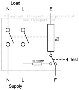
Internally, the device consists of a double pole switch, a solenoid (trip coil), test button and resistor.
The E terminal connects to an earth electrode in the ground. The F terminal connects to the exposed metalwork (or frame) of the installation, normally the main earthing terminal in the fusebox.
In normal operation, the voltage between the E and F terminals is negligible. In the event of a fault between line and any exposed metalwork, the voltage on the F terminal will rise towards the line voltage. The E terminal will be at or near zero volts, and as there is now a potential difference between the E and F terminals, the trip coil will operate, opening the double pole switch.
The coil is selected so that a voltage of 50 volts will operate the trip.
Test button
The test button temporarily connects the test coil to line via a small resistor, simulating a fault. Note that the F terminal is disconnected when the test button is pressed - this is to avoid any voltages appearing on the exposed metalwork of the installation during the test.
Significant flaws
While good in theory, in the real world, various situations can prevent the device from working.
The earth electrode must always have a reasonably low impedance, which can be difficult to achieve in well drained soils. The impedance will vary with weather and soil conditions.
The earth electrode must be positioned so that it's resistance area does not overlap that of other electrodes, water pipes, gas pipes or other earthed metalwork. In a street with multiple properties, this will be very difficult to achieve.
Overlapping with the resistance area of an electrode from a nearby installation can cause unwanted tripping due to faults in other properties. Overlapping with other earthed metalwork can prevent the device from working, as the alternate earth path will short out the trip coil. This could include items such as water or gas pipes, which will inevitably be connected to the F side of the trip coil via immersion heaters, boilers and other appliances inside the property.
Unlike a modern current operated RCD, these devices do not provide any protection against a person coming into contact with a live conductor. Faults between line and an earthed object such as a person will not cause any voltage to appear across the coil, and it will not trip.
Video explanation of these devices
This video explains how these devices were intended to operate, and several significant problems which can occur.


