Old Electrical Equipment - MK cooker switch and socket
Surface mounted plastic cooker switch with 13A socket outlet. Part numbers 6044 (top) and 6043 (base).
Part number / catalogue number for the complete assembly is 5040 IVY
30/50A cooker switch with socket outlet
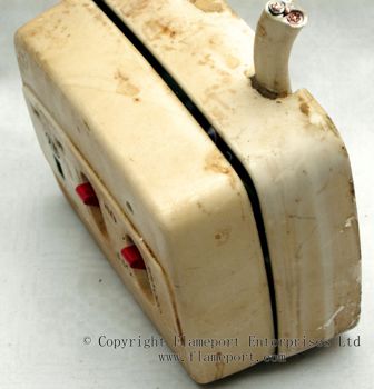
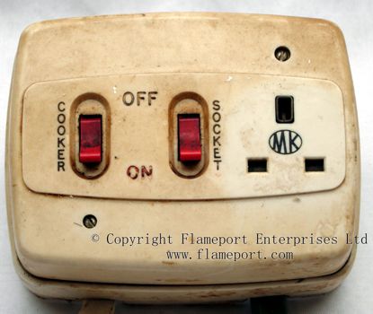 This revolting grease covered item is a combined cooker switch and 13A socket outlet. Surface mounted and made from plastic.
When new, this was a pale cream colour. Here it appears rather darker, due to the years of grease and dirt which no one bothered to clean away.
This would typically be connected to a 30A fused circuit, with the cooker permanently wired to the left switch. The other switch controls the socket outlet only, and is a left over from when this type of item was the only electrical outlet in the entire kitchen.
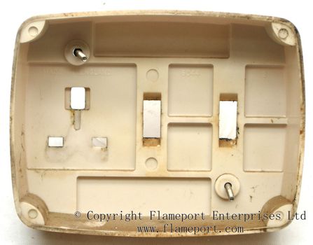
Back view
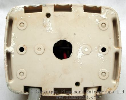
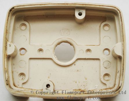 The back has various holes to allow wiring to enter from the wall behind and therefore not be visible. Alternatively, cables could enter on the surface by removing one or more sections from the edge.
In this case, both options have been used. Originally, cables entered via the round hole in the back. When found, some fool had removed this from the wall, connected two new cables via the surface holes and shoved the mess into the back of a kitchen cupboard underneath the new built in oven. It was not secured to the wall, cupboard or anything else.
That's right - these people had an entire new kitchen fitted which probably cost thousands of pounds, and yet whoever fitted it couldn't be bothered to replace the electrical wiring.
Back view
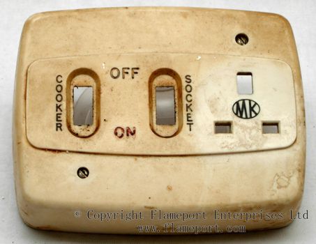 The front cover is a totally separate item, and contains no electrical parts at all.
Both the inside and outside are significantly yellowed and are covered in dirt.
The area where the plug fits is much cleaner, as a plug supplying the ignition for a gas hob was permanently fiited into it.
Inside
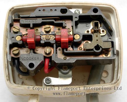
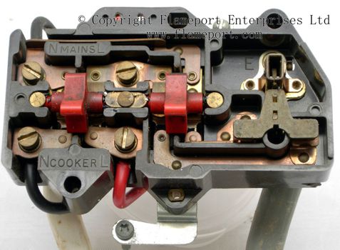 The internal mechanism is a separate component, and can be easily removed by undoing the two screws on the shiny metal strap.
A substantial amount of live metalwork is exposed, and the switch mechanism can be seen clearly.
The socket shutters are the usual sliding type, and are moved downwards by the top earth pin of the plug.
Back view of the internals
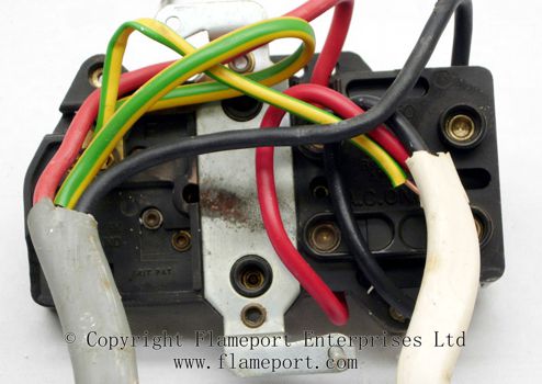
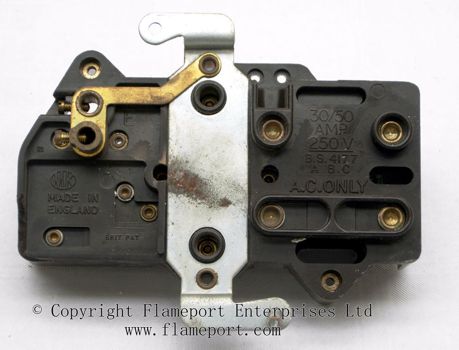 The earth terminals are on the back, and therefore it is necessary to remove the inner mechanism to connect the wiring.
Supply cables connect to the top terminals, and the cooker to the bottom terminals. Transposing these would result in the cooker switch working as expected, but the socket will only work when the cooker is on.
Moulded text on the back
30/50 AMP, 250V. BS4177, A.B.C. A.C. ONLY.
MK MADE IN ENGLAND
BRIT PAT.
Internals without wiring
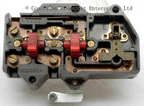 Another view of the internals, with wiring removed.
Both switches are double pole.


