Y plan with Unvented Hot Water Cylinder
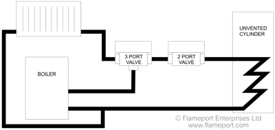
This uses the 3 port valve as with a standard Y plan, but adds a 2 port valve to stop flow to the hot water cylinder in the event of overheating.
An unvented cylinder is sealed under pressure, and overheating will cause the pressure inside to rise to dangerous levels. In extreme circumstances this can result in the cylinder exploding.
Traditional vented cylinders do not have this problem, as they are open to the atmosphere and water will be expelled via the vent pipe if the cylinder overheats.
Overview Video
This video covers the addition of a 2 port valve and high limit thermostat when installing an unvented hot water cylinder. View on Youtube.
Plumbing Overview
 The 2 port valve is installed on the output side of the 3 port valve, between the valve and hot water cylinder.
This is necessary as the 3 port valve defaults to hot water open in the event of no power or motor failure. This would result in water still circulating to the hot water cylinder if a fault occurred which caused the boiler to run continuously.
A 2 port valve defaults to closed with no power, and therefore stops the flow of water to the cylinder, preventing dangerous overheating.
Note that this diagram only shows the very basic arrangement of parts, and is NOT an accurate representation of an actual system.
System Wiring
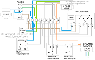
 Wiring is based on the standard Y plan, with the addition of a high limit thermostat and a 2 port motorised valve. These are shown at the bottom right of the diagram.
Output from the normal cylinder thermostat is connected to the high limit thermostat, and the output from that powers the 2 port valve motor. When the valve is fully open, a switch inside the valve connects the orange wire to line, and this orange wire is connected to the wiring centre to activate the boiler.
The high limit thermostat is normally closed. If the hot water cylinder overheats, the high limit thermostat opens and cuts power to the valve.
With no power, the valve will close as it has a spring inside. This stops the flow of water and also cuts power to the output wire which would normally stop the boiler and pump. However even in the event of the boiler continuing to run due to some other fault, no water can circulate and the cylinder will not continue to heat up.
2 Port Valve
The 2 port valve has 5 wires. Grey = line, blue = neutral, green/yellow = earth. These connect to the wiring centre terminals 1,2 and 3.
The brown wire is the input to the valve motor, and is connected to the output from the high limit thermostat.
Orange is the switched output which connects to terminal 8 in the wiring centre, and is what activates the boiler when heat is required.
Thermostat
Although shown as separate devices, the cylinder thermostat and high limit thermostat are normally combined into a single unit. However they have their own wiring terminals and are mechanically separate, so the failure of one does not affect the other.
Thermostat and valve are usually supplied with the unvented cylinder, although they can both be obtained separately if required.
New Installations
The arrangement shown here is most likely for an existing Y-plan system where the cylinder is being changed to an unvented one. For an entirely new installation, S-plan would be a far better choice, as that does not have the 'default open' problem and also allows the use of multiple zones for the central heating.


