Combination Boiler with Two Heating Zones - Universal
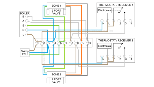
Wiring diagrams for two zone valves with a combination boiler.
This can be used with any boiler control voltage including 24V, volt free, 230V and others. The difference is that the zone valve switch is used to connect two terminals in the boiler together, rather than connecting 230V to one terminal only.
Overview Video
This is a continuation of the previous diagram that covers connections to boilers that do NOT have 230V inputs. View on Youtube.
Diagrams used in the video and further description continues below.
Overview
 All of the components and most of the wiring is identical to those used for the 230V switching arrangement.
The main difference is that the grey wire for both zone valves is connected to terminal 10 in the wiring centre, NOT to 230V as in the previous examples.
The boiler has two wires connected to it - shown as A and B here - connecting those together activates the boiler.
The two boiler wires connect to the orange and grey wires from both zone valves. When the valve is open, a switch inside connects those two wires together which activates the boiler.
Neither grey or orange are connected to 230V or anything else other than the boiler terminals.
Zone 1 active
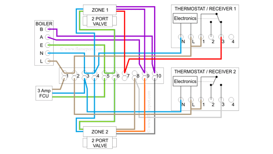
When heat is required for zone 1, the thermostat contact closes, which connects 230V to the output terminal 3. This is connected in the wiring centre terminal 7 to the zone valve, so the valve motor opens. (Highlighted in red).
Inside the valve, a switch inside connects grey and orange together. Grey and orange are connected to 9 and 10, and those are connected to the boiler A and B terminals. (Highlighted in purple)
The boiler heats the water and circulates it through zone 1 only - zone 2 does not heat up because the valve for zone 2 is closed.
The boiler terminals are connected together - NOT connected to any outside voltage source.
Zone 2 active
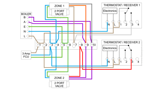
When heat is required for zone 2, the thermostat contact closes, which connects 230V to the output terminal 3. This is connected in the wiring centre terminal 8 to the zone valve, so the valve motor opens. (Highlighted in red).
Inside the valve, a switch inside connects grey and orange together. Grey and orange are connected to 9 and 10, and those are connected to the boiler A and B terminals. (Highlighted in purple)
The boiler heats the water and circulates it through zone 2 only - zone 1 does not heat up because the valve for zone 1 is closed.
The boiler terminals are connected together - NOT connected to any outside voltage source.
Both zones active
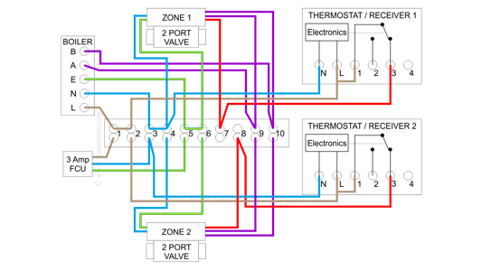
This is a combination of the two diagrams above. Both thermostats are active, which powers both 230V zone valve motors (red highlight).
Both valves open, and the switch in both valves connects orange and grey together (purple highlight).
The A and B terminals at the boiler are connected together which activates the boiler. Hot water is circulated through both zones, as both valves are open.
As with the other examples, no external voltage is applied to the boiler terminals - they are just connected together by the switch inside the zone valves.


