S plan
This scheme uses separate two-port valves, one for hot water and another for heating. It can be easily extended to include additional heating zones by adding an extra valve and room thermostat for each zone - this is typically called S Plan Plus.
This arrangement is common on new installations, as it allows for multiple heating zones with the minimum of additional plumbing and wiring.
2 Port Valve
The valve has two plumbing connections - in and out. With no power applied, a spring holds the valve closed so no water will flow.
Electrically, the valve has 5 wires:
- Green/Yellow, Earth - connected to the metal body of the valve.
- Blue, Neutral - internally connected to the neutral side of the motor.
- Brown, Live in - Activates the motor inside the valve
- Grey - Connected to one side of a switch inside the valve.
- Orange - Connected to the other side of a switch inside the valve.
When the valve is powered and reaches the fully open position, the grey and orange wires are connected together. This is normally used to activate the boiler and pump.
Overview Video
This video covers the wiring and electrical operation of an S plan system with two 2-port valves. Wiring diagrams and further information continues below. View on Youtube.
System Wiring
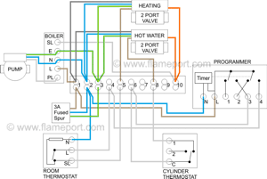
 This diagram shows the wiring layout using the most typical components. Here, coloured wires indicate the permanent mains supply to the boiler and programmer. The coloured valve wires are also shown.
Other wires are shown in pale grey. Some or all of these will be live depending on which modes are selected - these are highlighted brown in the other diagrams below.
These diagrams show a modern boiler where the boiler requires mains power all the time, with a separate wire used to activate the boiler and the pump connected directly to the boiler.
Older systems simply have the boiler and pump connected to SL (10 in the wiring centre), with only N and E permanently connected.
The room thermostat is shown with a neutral connection. However a 2 wire thermostat can also be used which does not require a neutral.
Unlke the Y-plan system, operation of hot water and heating are totally separate, and this layout can easily be extended to support additional heating zones simply by adding an extra valve and thermostat for each zone. It can also be adapted for use with underfloor heating.
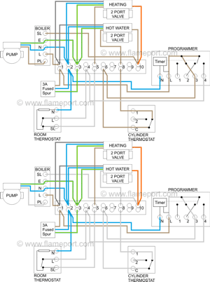
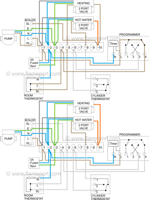
Operation - Hot water
 Power starts at terminal 3 (HW On) in the programmer. This passes via the wiring centre terminal 6 to the cylinder thermostat. If heat is required, power continues to terminal 8 in the wiring centre, and operates the motor in the hot water valve.
Once the valve is fully open, a switch inside connects the grey and orange wires together. Since grey is permanently connected to power, the orange wire provides power to terminal 10 in the wiring centre, and from there to the boiler and pump.
Operation - Heating
 Power starts at terminal 4 (CH On) in the programmer. This passes via the wiring centre terminal 4 to the room thermostat. If heat is required, power continues to terminal 5 in the wiring centre, and operates the motor in the central heating valve.
Once the valve is fully open, a switch inside connects the grey and orange wires together. Since grey is permanently connected to power, the orange wire provides power to terminal 10 in the wiring centre, and from there to the boiler and pump.
Operation - Hot water and central heating
This is simply the above two diagrams combined. Unlike the Y-plan system, operation of heating and hot water is totally separate, they do not interact or require the presence of the other.
Possible problems
The boiler and pump are switched via the valve. Therefore problems with the valve will mean the boiler never switches on, or in some cases will run continuously.
If the motor fails or the switch fails in the off position, the boiler will not operate.
If the switch fails on or the valve sticks open, the boiler will run all the time, regardless of the settings of programmer and thermostat. It will still run even if the programmer and thermostat are removed completely.


