Lighting Circuits - Overview
Basic overview of lighting circuits.
Three lights
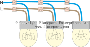
 This image shows three light bulbs (or more correctly, lamps), each connected to the mains. The supply contains two wires, Live and Neutral. Each lamp is connected to the live and neutral wires using some screw terminals.
This method of connection is called 'parallel', since each lamp has its own connection to the live and neutral supply. All of the live wires (brown) are connected together, amd all of the neutral wires (blue) are connected together.
Any number of lamps could be added to this arrangement, simply by extending the live and neutral wires to other lamps in the same way.
Problems
All of the lamps shown here are on. The supply is permanently connected, and the only method of control is to disconnect the supply, so that all of the lamps are off. This is useless in a real installation, since people will want to control each lamp separately. The different lamps could well be in separate rooms of a house.
Adding switches
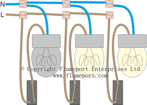
 In the real world, switches are used so that each lamp can be controlled separately. This diagram shows how three switches can be added, one for each lamp.
The live wire for each lamp now goes to a switch, then to the lamp. The switch has two terminals. When the switch is on, both of the terminals are connected together. When off, the terminals are not connected. This type of switch is called a one-way switch.
The first switch is off, so the first lamp is off. Note that the wire to the switch is still live, but the wire from the switch to the lamp is not.
The other two lamps are both on. Note that the wires to the switches are live, and the wires from the switches are live as well.
Switch wires are all live
The wires in these switches are ALL live. There are no neutral wires in any of them. This is a very important concept to understand.
The neutral connections to each lamp are permanent, and in this example do not go anywhere near the switches.


